Originally posted on: November 13, 2023
Designing an Efficient Vibratory Bowl Feeder: A Comprehensive Guide
Author: Adam Hallifax
Vibratory bowl feeders are essential components in various industries, providing a reliable and efficient method for sorting and orienting parts. They work by using vibration to move and align small objects or components, making them ready for further processing or assembly. Designing a vibratory bowl feeder involves careful consideration of several factors to ensure its effectiveness and efficiency.
In this article, we’ll explore the key steps and considerations in designing a vibratory bowl feeder.
STEP 1: Understanding the Components
- Bowl: The bowl is the main part of the feeder where the parts are placed. It is typically made of stainless steel and has a helical track or multiple tracks that guide and orient the parts.
- Drive Unit: The drive unit produces the necessary vibrations to move the parts. It typically consists of an electromagnetic coil and a spring system.
- Controller: The controller regulates the frequency and amplitude of the vibrations, allowing for precise control over the feeding process.
STEP 2: Determining Part Characteristics
Understanding the characteristics of the parts to be fed is crucial in designing an efficient vibratory bowl feeder. Consider the following aspects:
- Size and Shape: Parts with irregular shapes or sizes may require special considerations in bowl design to ensure proper orientation.
- Material: Different materials have varying friction coefficients and respond differently to vibration. This affects how parts move and orient within the bowl.
- Weight: Heavier parts may require more powerful vibrations, while lighter parts may need gentler movement.
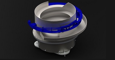 Bowl Top
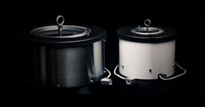 Drive Unit
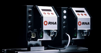 Controller
STEP 3: Selecting Bowl Geometry
- Bowl shape and size: Choosing the right bowl shape and size is crucial for optimal performance. The bowl’s shape should align with the parts being fed, ensuring they flow smoothly and consistently. Additionally, consider the size of the bowl in relation to the parts’ dimensions. A bowl that is too large may lead to inefficient feeding, as parts may not orient correctly, while a bowl that is too small can cause jams and hinder the feeding process.
- Track Configuration: Decide on the number and arrangement of tracks within the bowl. This depends on the desired orientation and feeding rate.
- Slope Angle: The angle of the bowl’s slopes affects how the parts move. Steeper slopes may be necessary for faster feeding rates.
- Track Width and Depth: These dimensions should be chosen to accommodate the size of the parts while preventing jams or clogs.
STEP 4: Designing the Base Unit
The base unit houses the electromagnetic coils and is responsible for generating the necessary vibrations. Key considerations include:
- Drive Unit Type: The drive unit is responsible for generating the necessary vibrations to move and orient the parts within the bowl, and they come in various types: half-wave, full-wave and high-speed electromagnetic drives. The choice between these drive units should be based on the specific requirements of the application, considering factors such as part material, size, and the desired level of precision in feeding.
- Spring System: Choose an appropriate spring system to balance the force generated by the coils and ensure stable vibration.
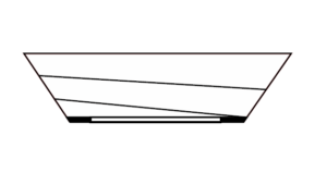
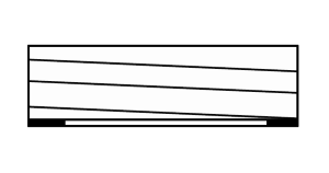 Cylindrical bowl
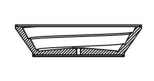
 Conical bowl
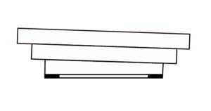 Stepped bowl
 Polyamide bowl (conical or stepped)
STEP 5: Implementing Controls
The control system is essential for regulating the frequency and amplitude of the vibrations. Consider the following:
- Variable Settings: Ensure that the controller allows for adjustments to accommodate different parts and feeding requirements.
- Feedback Mechanism: Consider implementing sensors or monitoring systems to provide feedback on the feeding process, allowing for real-time adjustments.
STEP 6: Testing and Optimisation
Once the feeder is assembled, thorough testing is crucial to ensure its performance meets the desired specifications. This may involve:
- Fine-tuning Parameters: Adjust vibration settings, track geometry, and other variables to achieve optimal feeding.
- Stress Testing: Assess the feeder’s performance under different loads and conditions to identify potential issues.
– Adam Hallifax, Sales Engineer at RNA Automation Ltd
Designing a vibratory bowl feeder requires careful consideration of various factors, from understanding the characteristics of the parts to be fed to fine-tuning the control system. By following these steps and conducting thorough testing, you can create an efficient and reliable feeder that meets the specific needs of your application. Remember that continuous monitoring and maintenance are essential to ensure long-term performance.
If you’re interested in streamlining your production lines with a new vibratory bowl feeder but unsure of where to start, give us a call on 0121 749 2566 to discuss your requirements.
Also available in:
![]() English (United States)
English (United States)
Last edited on: January 10, 2024