Key takeaway: A component that looks simple on the drawing board can behave very differently in motion. Recognising potential feeding challenges early—and working with experienced feeding system engineers—ensures that even the simplest parts move smoothly through automated production.
Scroll
Originally posted on: March 25, 2026
Why “Simple” Part Geometry Often Creates Complex Part Feeding Challenges
In automated part feeding systems, component geometry is often one of the biggest causes of feeding problems. While simple-looking parts may appear easy to handle, they frequently create challenges involving part orientation, instability, nesting and inconsistent presentation.
At RNA Automation, we’ve seen the opposite prove true time and again. Components such as washers, discs, caps, pins, or symmetrical plastic mouldings may appear straightforward at first glance, yet their lack of distinctive features can make reliable orientation and separation difficult. Understanding how part geometry affects feeding performance is essential when designing reliable feeding and handling systems.
1. Part Orientation Challenges Caused by Symmetrical Components
Many “simple” parts share one common trait: symmetry. While symmetry is ideal from a manufacturing standpoint, it can create ambiguity during automated feeding.
If a component looks identical from multiple orientations, a feeding system may struggle to determine which side should face up or forward. For example:
- A washer has no clear top or bottom.
- A cylindrical pin may look identical at both ends.
- A disc-shaped plastic component may rotate freely without presenting a consistent orientation.
Without distinctive geometry, the feeder must rely on subtle dimensional differences or secondary sorting mechanisms (e.g. precision sensors, vision systems) to orient the part correctly, which significantly increases the system’s technical overhead.
2. Parts That Stick, Nest, or Interlock
Another issue with simple geometry is the tendency for parts to interact with one another in unpredictable ways.
Flat or hollow components often:
- Nest together (e.g. cups or caps stacking inside each other)
- Stick together due to static or surface tension
- Interlock mechanically, especially when edges or grooves are present
When this happens inside a feeder bowl or hopper, the flow of components becomes inconsistent, causing jams, reduced output, or unstable feed rates.
Preventing this requires sophisticated track pressure relief and specific vibrations that wouldn’t be necessary for a more “complex” part with a natural standoff.
3. Lightweight Parts and Unstable Movement
Small plastic components or lightweight metal parts may also behave unpredictably inside vibratory or centrifugal feeding systems.
Low mass can lead to:
- Erratic movement on vibratory tracks
- Parts bouncing or flipping unexpectedly
- Inconsistent positioning during transfer to downstream processes
In these situations, the feeding system must carefully balance vibration amplitude, track geometry, and tooling design to maintain stable part flow.
4. How Component Tolerances Affect Feeding Performance
With simple parts, small dimensional variations can have a large impact on feeding performance.
When features are minimal, feeding tools often rely on very tight tolerances to sort or reject incorrect orientations. Even minor changes in moulding quality, burrs, or surface finish can alter how the part behaves inside the system.
This is why early evaluation of part geometry is critical during the design stage of any automated feeding solution.
 Washers: No distinct top or bottom
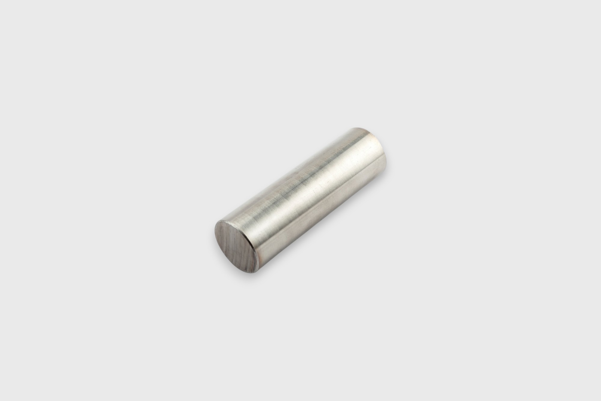 Pins: Identical ends with no visual orientation.
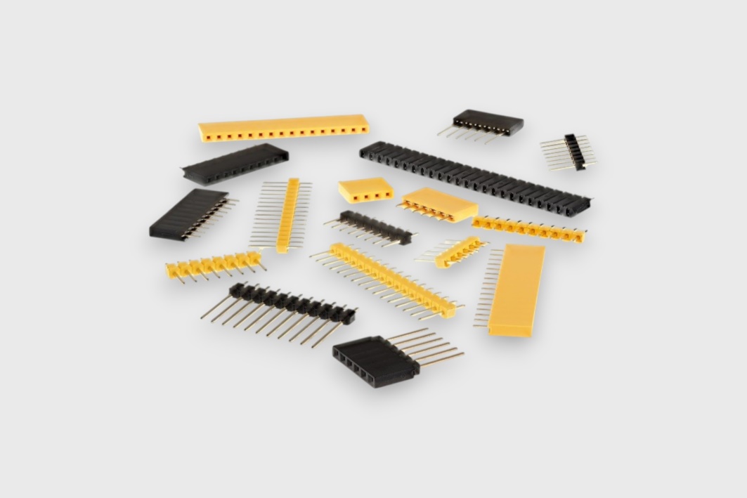 Connectors: Tangling via grooves or edges.
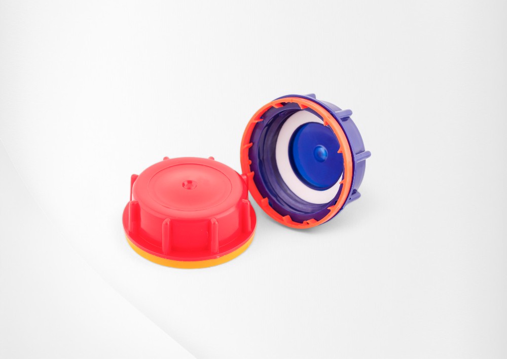 Caps: Parts stacking
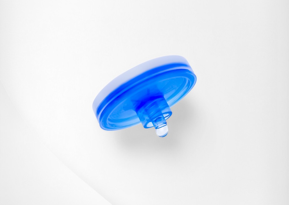 Syrings Filters: Free rotation with no fixed reference points
📩 Have a challenging part? Contact us today for a free feasibility study
📞 Or call us on +44 (0)121 749 2566 to discuss your project.
📞 Or call us on +44 (0)121 749 2566 to discuss your project.
The Importance of Feeding Expertise
 Because of these factors, reliable feeding rarely comes from the component geometry alone. It depends on carefully engineered feeding and handling systems that account for the behaviour of the part in motion.
At RNA, part feeding challenges are typically evaluated at an early stage of the project. Engineers review factors such as:
- Part geometry and symmetry
- Surface finish and material properties
- Part weight and centre of gravity
- Potential nesting or tangling behaviour
- Required orientation and output speed
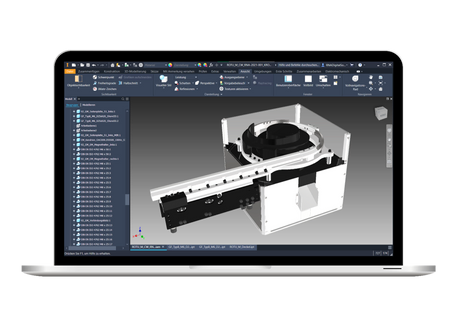
This early analysis helps identify potential feeding risks before tooling is produced. In many cases, digital tools such as RNA’s Digital Feeder™ simulation can be used to model part behaviour and optimise track design prior to manufacture.
By analysing how parts interact within the feeding system, engineers can reduce trial-and-error during commissioning and improve the stability of the final solution.
When “Simple” Requires Smart Engineering
In practice, many successful automation projects rely on specialised feeding technologies to handle deceptively simple components. These may include vibratory bowl feeders, centrifugal feeders, multi-lane linear feeders, flexible feeding systems or digitally simulated feeding solutions designed to optimise orientation and flow.
At RNA Automation, these systems are designed with a focus on part behaviour, process stability, and integration with downstream equipment. The goal is not simply to move components, but to ensure consistent orientation, controlled flow, and reliable delivery to the next stage of production.
For parts with limited geometry or high symmetry, the engineering of the feeding track, tooling features, and transfer interfaces becomes particularly critical. Careful optimisation of these elements allows even the most visually simple parts to be fed reliably at production speeds.
Understanding these challenges early in the design process helps ensure that the feeding system supports stable, repeatable manufacturing performance.
👉 Stop Guessing, Start Orienting.
Don’t let “simple” parts bottleneck your production line. Our engineers specialise in turning geometry headaches into high-speed realities.
FAQs
Also available in:
 English (United States)
Last edited on: June 2, 2026
