Originally posted on: February 19, 2024
Vibratory Bowl Feeder Tooling Design: Optimising Performance
Author: Adam Hallifax

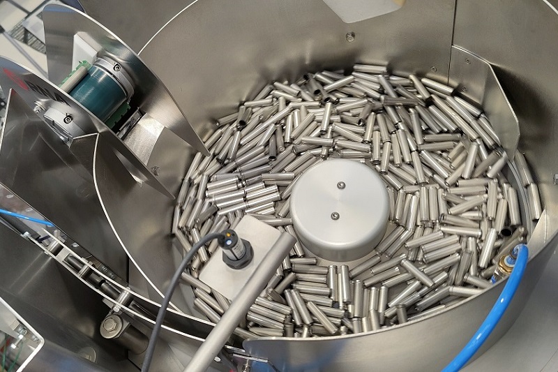
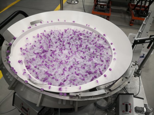
Vibratory bowl feeder tooling design plays a critical role in achieving consistent part orientation, reliable feed rates and efficient automated production. While the feeder’s drive unit provides the vibration needed to move component parts, the tooling determines how parts are separated, selected and presented to downstream equipment.
Effective tooling design must consider part geometry, selection methods, production speed and material characteristics. Poorly designed or worn tooling can lead to incorrect orientation, part jams, inconsistent feeding and unnecessary downtime.
What Is Vibratory Bowl Feeder Tooling?
Bowl feeder tooling refers to the customised features incorporated into a vibratory bowl feeder to control part movement, selection and orientation. According to RNA’s Sales Manager:
Good tooling should give efficient part selection and reliable feed rates while causing the least noise or damage to parts.
Why Is Tooling Design Important for Bowl Feeder Performance?
- Improve Part Orientation: Guide and select parts into the required position.
- Maintain Consistent Feed Rates: Reduce interruptions caused by jams or unreliable selection.
- Minimise Part Damage: Control impacts and contact with feeding surfaces.
- Improve Feeding Reliability: Reduce misfeeds and unnecessary part recirculation.
- Support Maintenance: Simplify inspection, adjustment and replacement of tooling features.
The objective is to achieve reliable part presentation without introducing unnecessary mechanical complexity.
For an overview of the bowl itself, see What Is a Bowl Feeder and How Does It Work?
SPOTLIGHT
Discover RNA Lifecycle Services
Our team of highly skilled service engineers leverages decades of automation experience to address your maintenance needs promptly.
● Bowl Feeder Relining
● Refurbishing
● Spare Parts
● Servicing
Get started >
7 Key Factors in Vibratory Bowl Feeder Tooling Design
1. Part Geometry and Feeding Behaviour
Part geometry is one of the most important considerations in bowl feeder tooling design.
Size, shape, weight distribution, surface characteristics and dimensional tolerances influence how parts move and settle on the feeding track.
Complex or irregularly shaped parts may require specialised guides and selection features. However, even simple component parts can present feeding challenges.
Accurate part drawings, CAD models and physical samples help engineers assess feeding behaviour and develop suitable tooling geometry.
2. Part Orientation and Selection Methods
The selection method determines how incorrectly positioned parts are identified, rejected or repositioned.
Common selection methods include:
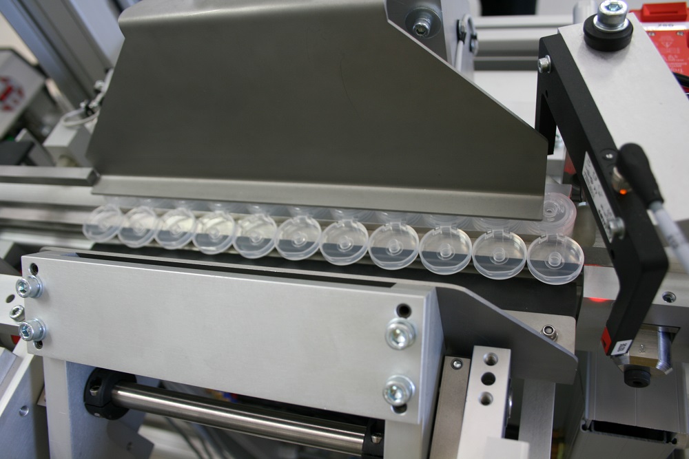
- Mechanical Selection: Rails, slots, steps and guides that allow correctly orientated parts to continue while rejecting unsuitable positions.
- Air-Jet Selection: Precisely controlled air jets used to reject or reposition component parts.
- Sensor-Based Selection: Sensors that identify component presence, position or orientation and trigger a reject or accept action.
- Vision-Assisted Selection: Camera systems that identify orientation features and provide information for automated selection or handling.
The most effective approach depends on part geometry, required orientation and production speed. Some applications use multiple selection methods to achieve reliable results.
3. Feed Rate and Production Requirements
Tooling design directly influences the number of correctly orientated parts a feeder can deliver.
Achieving high production rates requires carefully designed selection stages, controlled track clearances, and, where appropriate, merging streams into a consistent flow.
However, increasing vibration alone does not necessarily improve throughput. Excessive speed can cause unstable part movement, misorientation or jamming.
Tooling must therefore balance feeding speed, orientation reliability and part stability to achieve the required production output.
4. Simplicity of Design
Overly complex tooling can increase manufacturing costs and make maintenance more difficult.
Where possible, tooling should use straightforward, accessible features that can be inspected, cleaned and adjusted without unnecessary dismantling.
Modular or interchangeable tooling may also be beneficial where a feeding system needs to accommodate product variations.
A well-designed system balances the complexity required for reliable orientation with practical maintenance requirements.
5. Tooling Materials and Operating Environment
Tooling materials must be selected according to part characteristics and operating conditions.
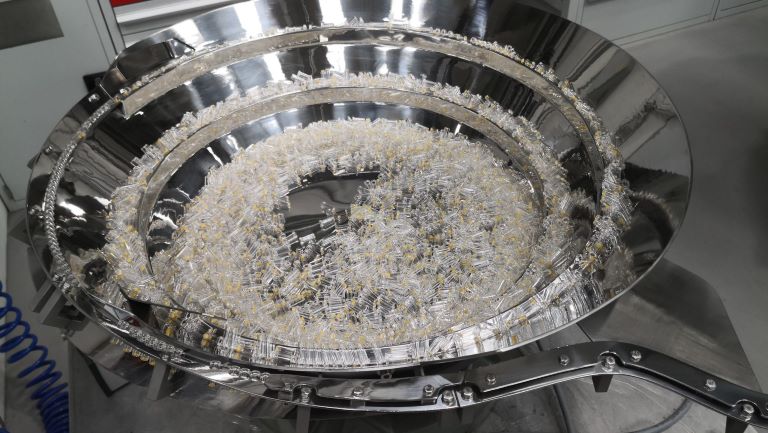
RNA bowl feeders can be manufactured from materials including stainless steel, aluminium and polyamide, with suitable tooling materials and surface finishes selected for each application.
For example, pharmaceutical applications may require high-grade stainless steel, appropriate surface finishes and particular attention to cleanability.
Heavy-duty industrial applications may place greater emphasis on mechanical durability and wear resistance.
Material selection should consider both feeding performance and the environment in which the equipment operates.
6. Noise and Impact Reduction
Excess noise can indicate repeated part impacts, unsuitable tooling contact or inappropriate operating conditions.
Tooling design can help minimise these effects by controlling part movement and reducing unnecessary collisions.
Durable linings, such as polyurethane, can provide cushioning and reduce impact noise in suitable applications. Our Bowl Feeder Relining service covers existing bowls.
However, noise and component part damage should be assessed across the complete feeding system, including the drive unit, bowl construction, part material and operating speed.
7. Surface Coatings and Wear Resistance
Tooling surfaces influence friction, part movement and long-term feeding performance.
Depending on the application, specialist coatings may be used to:
- Tune friction, adding grip for unstable parts or promoting sliding where needed.
- Reduce scratching or marking.
- Protect tooling surfaces against abrasion.
- Reduce galling or unwanted metal-to-metal contact.
For more, read Feeder Coatings Explained.
Coating selection should be considered during tooling design rather than treated solely as a finishing process.
Can Existing Bowl Feeder Tooling Be Modified?
Tooling requirements may change during a feeder’s operating life.
Changes to part geometry, production output or downstream equipment can affect feeding performance, even when the original feeder remains mechanically sound.
In suitable cases, bowl feeder retooling or tooling modifications can restore performance or accommodate new part requirements without replacing the complete feeding system.
Potential modifications include adjusting orientation features, replacing worn guides, modifying selection tooling or renewing specialist coatings.
An engineering assessment can determine whether the existing equipment is suitable for modification. Contact us with part samples or drawings and your target feed rate.
FAQs About Bowl Feeder Tooling
📩 Discuss Your Bowl Feeder Tooling Requirements
Whether you are developing a new feeding system, experiencing inconsistent part orientation or considering modifications to existing equipment, effective tooling design is essential for reliable performance.
Contact us today to discuss your vibratory bowl feeder tooling requirements and explore suitable engineering solutions.
📞 Or call us on +44 (0)121 749 2566
Also available in:
 English (United States)
Last edited on: November 9, 2026
